| ITOH DENKI Hongkong Vietnam | PM500FE-17-387-D-024-JD-P2 - Roller Dia.: 50mm - Roller Overall Length: 397mm - Cable (L): 300mm - Transport Speed: 17M/min. - c/w D-Shape Shaft - c/w Two Grooves (50+32) - c/w High carbon steel with Zinc coating Pipe - c/w Mounting Bracket No. A-001 (2pcs.) - w/o Control Card |
| ITOH DENKI Hongkong | Control Card
HB-508S - c/w 2P, 3P & 5P Connector (HB-508S) - c/w 800mm Communication Phone Cable |
| ITOHDENKI | Circuit
Board CBM-105FN DC24V |

GNN Việt Nam chuyên phân phối ITOH DENKI MOTOR Drum Gear Motors, GearBoxes, Gear Motor, AC, DC Motor tại Vietnam
Chủ Nhật, 6 tháng 7, 2014
List hàng Itoh Denki Vietnam | Control Card HB-508S | Itoh Denki Việt Nam
Thứ Bảy, 5 tháng 7, 2014
ITOH DENKI Vietnam | PM500FE-17-387-D-024-JD-P2 | ITOH DENKI Việt Nam
| Brand: ITOH DENKI | |
| Circuit Board | |
| CBM-105FN DC24V | |
| ITOH DENKI MOTOR (Nhật) Chuyên cung cấp Drum Gear Motors, GearBoxes, Gear Motor, AC, DC Motor | |
| ITOH DENKI Hongkong | PM500FE-17-387-D-024-JD-P2 - Roller Dia.: 50mm - Roller Overall Length: 397mm - Cable (L): 300mm - Transport Speed: 17M/min. - c/w D-Shape Shaft - c/w Two Grooves (50+32) - c/w High carbon steel with Zinc coating Pipe - c/w Mounting Bracket No. A-001 (2pcs.) - w/o Control Card |
| ITOH DENKI Hongkong | Control Card HB-508S - c/w 2P, 3P & 5P Connector (HB-508S) - c/w 800mm Communication Phone Cable |
| ITOHDENKI | Circuit
Board CBM-105FN DC24V |
Thứ Tư, 2 tháng 7, 2014
ITOH DENKI appoints Richard R. Kosik as President of US operation
ITOH DENKI appoints Richard R. Kosik as President of US operation
ITOH DENKI, a world leading manufacturer of MDR motorized conveyor rollers, announced the appointment of Richard R. Kosik to the position of President of ITOH DENKI USA, INC effective August 21, 2013.
Kosik has been with the company for 17 years since its inauguration and has brought enormous success in penetrating the U.S. market with the innovative energy efficient conveyor motorization technology for the logistics industry. Previously, Kosik held various management positions in the company including National Sales Manager and Senior Vice President.
“With his long experience in material handling industry and with his excellent sales & marketing skills, I look forward to continued success and growth” said Kazuo Itoh, Chairman and CEO of the ITOH DENKI group.

Itoh Denki USA unveils new products at the 2014 MODEX Show in Atlanta,GA ITOH DENKI Vietnam | ITOH DENKI Việt Nam
Itoh Denki USA unveils new products at the 2014 MODEX Show in Atlanta,GA


Click On Images for Information


ITOH DENKI Vietnam | ITOH DENKI Việt Nam
STATIC LOAD TABLE

IMPACT LOADING:
In applications where the article being transferred is dropped onto the POWER MOLLER, reduce static load limits in the above table by 50% to compensate for the increased forces generated from impact. As the load limit will vary considerably in accordance with the intensity of impact, allow a substantial margin of safety.
CHANGE IN TRANSPORTING SPEED:
The peripheral velocity (transportation speed) of the POWER MOLLER is dependent upon the weight and material composition of the load as well as the ambient temperature. Please contact your Itoh Denki representative for additional technical information.
Care should be taken to avoid exposing the POWER MOLLER too excessive shock as a result of drastic load speed changes with-in a line or between adjoining lines. Although depending on the weight and speed of the load, typically no harm is done by load speed changes within 50% of nominal POWER MOLLER speed. Also slave driving idlers and load weights can have an effect on the speed of the POWER MOLLER.
INVERTER USE:
When using a frequency inverter / variable frequency drive for AC rollers Itoh Denki recommends utilizing a surge protector into the line to decrease the possibility of high voltage spikes.
Note – change in frequency may affect performance.
Safe operating frequencies

ITOH DENKI Vietnam | ITOH DENKI Việt Nam
LOCKING:
As a special outer rotor is used for the Power Moller's motor, the coil will not burn out when the POWER MOLLER is locked under conductance for a short period of time. But repeated locking will raise the temperature of the motor coil and result in gradual deterioration of the insulation and eventually cause the motor to burn out. It’s unnecessary to turn off the power when the POWER MOLLER is locked under conductance for a few seconds. However, if locking longer than 10 seconds is required, it is necessary to turn off the power or use the accumulation type.

CONTACT TIME / CYCLE TIME / DUTY CYCLE:
Due to temperature rise of the coil winding, the minimum contact time during intermittent operation is approximately as specified below:

Example:DUTY CYCLE= TIME ON / TIME ON + TIME OFF
DUTY CYCLE = 20 SECONDS ON / 20 SECONDS ON + 20 SECONDS OFF DUTY CYCLE = 0.5 OR 50%
TEMPERATURE RISE:
The POWER MOLLER is designed to operate within an ambient temperature of -10°‑ C (14°‑ F) to 40°‑ C (104°‑ F). The temperature of the roller tube rises about 20°‑ C (68°‑ F) above the ambient during normal usage. Please contact your Itoh Denki representative for information on additional POWER MOLLER models.
INERTIA AND INTERMITTENT OPERATION:
A. As a result of motor inertia, the POWER MOLLER will not instantly stop rotating after the power is disconnected.
B. Inertia values differ in accordance with motor type, speed, operation time as well as weigh of the load.
C. Inertia can be eliminated by using the POWER MOLLER with built-in brake
BRAKE INFORMATION:
In automated conveyor lines, it is sometimes necessary to precisely stop or position the article being transferred. In these cases, the optional built-in electromagnetic brake should be used.
- When not powered, the built-in electro-magnet uses spring force to lock the motor and prevent the tube rotation. The motor is released when the brake is powered (energized). Ordinarily, the power to the brake and motor is controlled simultaneously.
- In most cases, an external mechanical stop can be eliminated by using the POWER MOLLER with the built-in brake. However, the stopping distance may vary slightly depending on the load, speed, etc.
In gravity lines, it is often necessary to control the descent of the load to prevent damage to the articles accumulated at the end of the line. In this case, the standard POWER MOLLER can act as a brake roller.
- When the rotation speed of the POWER MOLLER is increased by 10-20% from its nominal speed, it functions as an induction generator and braking torque is applied to the load.
- By incorporating POWER MOLLERs at several points in a self-traveling gravity line, speeding or congestion of the loads will be prevented.
Braking characteristics vary by POWER MOLLER model and weight transferred.
Please contact your Itoh Denki representative for additional information.
LEVEL OF CONVEYING SURFACE:
1. If the bottom surface of the load is not flat or the conveyor rollers are not level, then the POWER MOLLER may rotate freely and the load may not be transferred or may tend to drift. It is especially important when transferring relatively heavy loads that the static load limit of the POWER MOLLER is not exceeded.
2. Transferring light loads (less than 5kg) may be impeded by the resistance of idler rollers. Check to be sure that the idlers spin freely.
3. Due to packing (binding) bands, bulging of the bottom of the load, etc., the load may lean to one side during transfer. The use of rubber lagging on each end of the POWER MOLLER would facilitate a straight transfer of the load.
- When the diameters of the roller tube and the shafts of the POWER MOLLER are the same as that of idler rollers, the existing shaft holes in the conveyor frame can be used without any modification.
- If these dimensions are not the same, the level of the POWER MOLLER must be adjusted by hanging the height of the shaft holes in the frame so that the load will be evenly applied to all the rollers.
WARNING: Please Review Prior To Installation Fittings ITOH DENKI Vietnam | ITOH DENKI Việt Nam
WARNING: Please Review Prior To Installation
Fittings ITOH DENKI Vietnam | ITOH DENKI Việt Nam

How To Select A Power Moller Fittings ITOH DENKI Vietnam | ITOH DENKI Việt Nam
How To Select A Power Moller Fittings ITOH DENKI Vietnam | ITOH DENKI Việt Nam

1 – Material: What is in contact with the Motorized Roller?
- Metal
- Plastic
- Wood
- Urethane
- Natural rubber
- Corrugated cardboard
- Other material
2 – Product weight: What will be the maximum weight?
3 – Available voltage: What voltage are you using?
- 24VDC
- 3 230VAC @ 60Hz
- 1 115VAC @ 60Hz
- Other Voltages
4 – Desired transportation speed: How fast do you want to move the article?
- Feet/minute (FPM)
5 – Diameter of the roller: What diameter are you looking for?
Common Itoh Roller Diameters
Common Itoh Roller Diameters
- 1.50” (38.0mm)
- 1.68” (42.7mm)
- 1.91” (48.6mm)
- 2.25” (57.0mm)
- 2.38” (60.5mm)
- 2.50” (63.5mm)
- 3.00” (76.3mm)
(Convert English units to Metric units, 1 inch=25.4 mm)
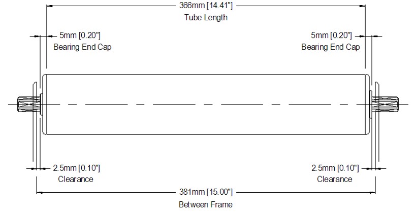
6 – Between frame dimension: What is your between frame dimension (BF)?
- In determining the correct length of the Power Moller required, you should first obtain the between the frame width of the conveyor you will be mounting the Power Moller in.
- All dimensions need to be converted to millimeters.
- Take the between the frame width and subtract 15mm to account for bearing end caps and clearances to achieve proper tube length.
- Subtract 21mm when using the “JQ” type shafts.
- For the PM635FS the deduction will be 20mm
- For PM763BS deduct 30mm
- For IP-G and HP-G rollers, deduct 35mm.
7 – Options: Does the application call for any special options?
- Lagging (Natural Rubber, NBR, Neoprene, Urethane)
- Dust-proof
- Waterproof
- Brake
- Clutch
- Other
- KF – Brackets not ordered with roller
Important Formulas:
Tangential Force (TF)
- Tangential force is the force in lbs. that is needed to move the item on the conveyor.
- The force tangent to the roller’s surface.
- Tangential force F can be found by the following formula:
Formula 1
TF = µ X W
TF = Required tangential force
W= Weight of article to be transferred
µ = Coefficient of rolling friction in accordance with the material composition
of the bottom of the article to be transferred. (See Table I)
TF = µ X W
TF = Required tangential force
W= Weight of article to be transferred
µ = Coefficient of rolling friction in accordance with the material composition
of the bottom of the article to be transferred. (See Table I)
- To determine the number of POWER MOLLER units required for transfer, compare required tangential force (F) and the tangential force of one POWER MOLLER unit (f)
Formula 2
Number of POWERMOLLERS required = F/f
Number of POWERMOLLERS required = F/f

The above values are based on industry standards of products with a smooth, uniform bottom surface in contact with the roller.
Example
- Material: Cardboard
- Weight: 25 lbs.
- Voltage: 3Phase, 230VAC @ 60Hz
- Speed: 85 FPM
- Diameter: 2.25”
- BF: 24”
- Options: None
A – Tangential force required (Formula 1)
Given W = 25 lbs.
Cardboard coefficient = 0.11
TF = X W
TF = 0.11 X 25 lbs.
Cardboard coefficient = 0.11
TF = X W
TF = 0.11 X 25 lbs.
TF = 2.75 lbs. required to move the article
PM570AS-20 TF – 5.4 lbs. > 2.75 lbs. ((Refer to catalog page for chosen roller to obtain performance data)
PM570AS-20 TF – 5.4 lbs. > 2.75 lbs. ((Refer to catalog page for chosen roller to obtain performance data)
B – Match/Best fit the diameter
- Diameter given 2.25” (57.0 mm)
- Model: PM570
C – Given AC motor type
- Model number/motor type reflects AC or DC
- PM570AS
D – Select the best speed for the customer
- Speed code is an approximate meter-per-minute figure
- Varies by model
- Reference FPM values
- See speed table for PM570AS, (Refer to catalog page for chosen roller to obtain speed codes)
- Given 85 FPM, Speed code -20 offers 89.6 FPM
Model number with speed code: PM570AS-20
E – Maximum Load Limit
- See maximum static load limit table, page 60
- PM570 series
- 500 – 600 mm tube length
- Maximum load limit of 176 lbs. per roller
- 25 lbs. load < 176 lbs. limit – Okay
F – Select the correct voltage
PM570AS is an AC motor type
PM570AS is an AC motor type
- Available voltage is 3 phase, 230VAC @ 60Hz
- Model number with voltage – PM570AS-20-595-3-230
G – Options
- No options given
Final model number: PM570AS-20-595-3-230
Description
- 2.25” Diameter
- Standard AC motor type
- 90.1 FPM
- 595 mm Tube Length
- 3 230 VAC @ 60 Hz
- No Options
F-RAT 24 VDC Right Angle Transfer Fittings ITOH DENKI Vietnam | ITOH DENKI Việt Nam

F-RAT
24 VDC Right Angle Transfer Fittings ITOH DENKI Vietnam | ITOH DENKI Việt Nam
Specification Document
| F-RAT-S Product Sheet |
CAD Drawing Download (.DWG)
| F-RAT-S .DWG File |
Dimensions
Features:
F- RAT specifications
- Drop in Installation into existing MDR frames
- Three Motors –Spine (belts), Lifting/Dropping Mechanism, Transfer Rollers
- Controlled with Itoh Denki’s IB 4 zone cards
- Minimum Package Size: 300mm (11.81”) x 300mm (11.81”)
- Minimum Height: 170 mm (6.69”)
- Transfer Capacity: 2500/hr (Based on 13.8” x 15.4”, 66lb package)
- Available in the following standard sizes:
Size A – 15”wide X 30” long
Size B – 20” wide X 30” long
Size C – 24” wide X 30” long
Size D – 28” wide X 30” long
Size B – 20” wide X 30” long
Size C – 24” wide X 30” long
Size D – 28” wide X 30” long
Basic Specifications
- Roller Diameter: 50.0 mm
- Size BF Width (W) Transfer direction: 15″, 20″, 24″, 28″
- Length (L) Spine direction: 30″
- Height: 170mm (6.69″)
- Transfer / Spine Speed: 56, 197, 295 FPM
- Stroke: 10mm (0.39″)
- Power voltage: DC24V
- Ambient temperature: 0 ~ 40℃ (No freezing)
- Humidity: Below 90%RH (No condensation)
- Atmosphere: No corrosive gas
- Vibration: Below 0.5G
- Installation: Indoor
Molded Extension Cables Fittings ITOH DENKI Vietnam | ITOH DENKI Việt Nam
Molded Extension Cables Fittings ITOH DENKI Vietnam | ITOH DENKI Việt Nam

Specification Document
 | Molded Extension Cables Product Sheet |
Drawing Download (.DWG)
 | Extension Cables .DWG File |
Features:
Available only for DC Power Mollers that require extra cable length
Cables available in the following standard lengths:
- 600mm (23.62″), 1200mm (47.24″), 2200mm (86.61″) and 2700mm (106.30″)
Allows for easy hook up between Power Moller roller cable and driver card
Available in the following configurations:
- 9 pin male to 9 pin female
- 9 pin male to 10 pin female
- 10 pin male to 10 pin female
- 12 pin male to 12 pin female
Dimensions:
")
Snap-In-Drive (SID) Fittings ITOH DENKI Vietnam | ITOH DENKI Việt Nam

Snap-In-Drive (SID) Fittings ITOH DENKI Vietnam | ITOH DENKI Việt Nam
1.91″ (48.6mm) Diameter (24V DC)
The SID (Snap-in-Drive) interface controller is a new generation, built-in ZPA-logic, control card. It is compatible with the SID series Power Moller® motor driven roller with internal drive card (XE / XP with cable-less option).
The SID controller design concept minimizes installation and wiring time by employing a unique mounting method. It also has several operating modes and speed options which make the SID controller suitable for most ZPA applications, even merge and divert areas.
Features
- RoHS and EMC conformity (EN61000-6-2/1999, EN61000-6-4/2001)
- Input power voltage: DC24V ±10%
- LED indicators for Power, Sensor, and Error status
- Speed adjustable by potentiometer, 10 different settings (Interface card only)
- 4 DIP switches for operation selection (Interface card only)
- Built-in diode for reverse polarity protection
- Flexible-Zone-Recognition for product that spans multiple zones (slug release mode)
Product Sheet
| SID Product Sheet |
Application Document
 |
Đăng ký:
Bài đăng (Atom)